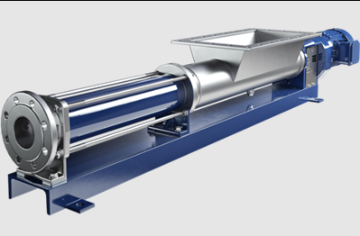
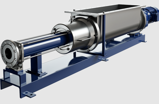
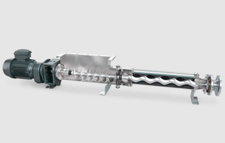
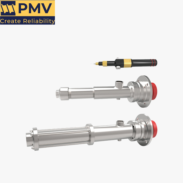
Progressive cavity pumps are essential in various industries due to their ability to handle viscous fluids and provide a steady flow. The design of the micro interface for these pumps plays a crucial role in enhancing their functionality and usability. This article explores the key aspects of micro interface design for progressive cavity pumps, highlighting its importance, components, and best practices.
Importance of Micro Interface Design
The micro interface serves as the bridge between the user and the pump system. A well-designed interface can significantly improve user experience, operational efficiency, and maintenance procedures. Key reasons for prioritizing micro interface design include:
- User Engagement: An intuitive interface encourages users to interact effectively with the pump, reducing the learning curve.
- Operational Efficiency: A streamlined interface allows for quick adjustments and monitoring, enhancing overall performance.
- Error Reduction: Clear visual cues and feedback can minimize operational errors, ensuring safe and precise pump management.

Components of the Micro Interface
The micro interface for progressive cavity pumps typically consists of several essential components:
- Display Screen: A digital screen that presents real-time data, such as flow rate, pressure, and temperature.
- Control Buttons: Physical or virtual buttons for adjusting settings, starting or stopping the pump, and navigating through options.
- Status Indicators: Visual indicators (like LEDs) that show the pump’s operational status, alerts, or maintenance needs.
- Connectivity Options: Interfaces for communication with external devices or systems, enabling remote monitoring and control.
- User Manual Access: An integrated help section or quick access to manuals for troubleshooting and guidance.
Best Practices in Micro Interface Design
To create an effective micro interface for progressive cavity pumps, several best practices should be followed:
- Simplicity: Keep the design clean and uncluttered. Limit the number of buttons and options to what is necessary for operation.
- Consistency: Use a consistent layout and terminology throughout the interface. This helps users quickly familiarize themselves with the system.
- Visual Hierarchy: Organize information logically, with the most critical data prominently displayed. Use color and size to differentiate between normal and alert conditions.
- Feedback Mechanisms: Implement visual or auditory feedback for user actions. This reassures users that their inputs have been registered and understood.
- Responsive Design: Ensure that the interface adapts well to various screen sizes and devices. This is particularly important for mobile applications used in the field.
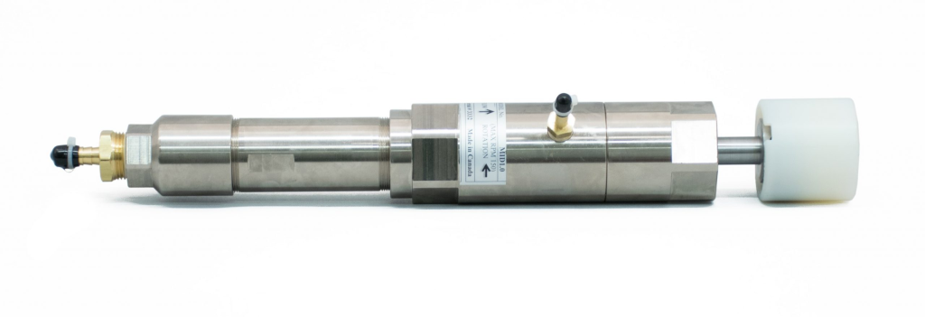
Conclusion
The micro interface design of progressive cavity pumps is a vital aspect that influences user interaction and operational efficiency. By focusing on simplicity, consistency, and effective feedback mechanisms, designers can create an interface that enhances the overall experience for users. As technology continues to evolve, the integration of advanced features like remote monitoring and smart connectivity will further improve the usability and functionality of these essential pumping systems.
People also ask
Send Your Enquiry :

