-
-
-
Pump Screw-PMV Pump
People Also Ask
-
-
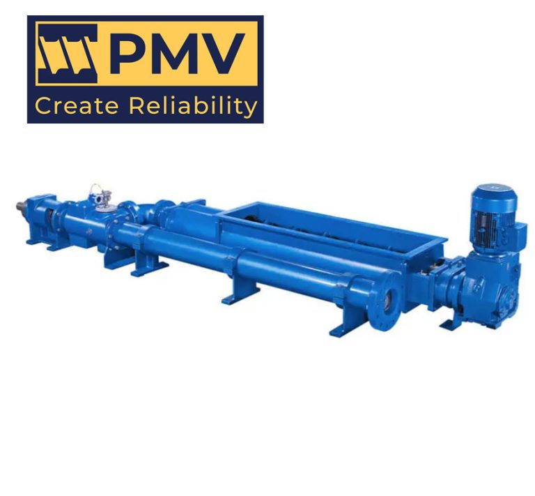
PMV Progressing Cavity Pump Manufacturers
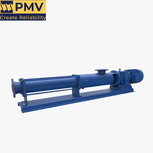
What is PMV Progressing Cavity Pumps Manufacturers? PMV Pump Manufacture Co., Ltd was founded in 2003, is a professional pump enterprise integrating research, development, production, sales and service. Since its inception, quality management has always been the first goal. Therefore, we have designated staff responsible for raw material composition inspection, pump case bulge test, performance…
-
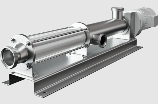
Type of Screw Pump-Pumpvv
What is a screw pump? Screw pump is a part of the dry compressed gas transfer pump series. They are positive displacement pumps that use one or more screws to move fluid or water along the screw shaft. These screws interlock to pressurize the fluid and move it into the system. These screws engage each…
-
Screw Pump-Pumpvv
The Description of Screw Pump A screw pump is a type of positive displacement pump that utilizes an intermeshing screw and housing to transfer fluids or viscous substances. The pump consists of two or more screws (also known as rotors) that rotate in opposite directions, creating chambers that trap and move the fluid along the…
-
Screw Pump Diagram
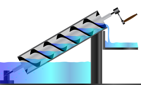
Introduction to Screw Pump Diagram. A screw pump diagram is a schematic representation of the working principle and components of a screw pump. Screw pumps are positive displacement pumps that use rotating screws to move fluids or slurries through a system. They are widely used in various industries due to their ability to handle high…
-
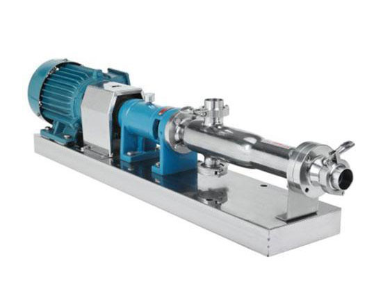
Hygienic Twin Screw Pump
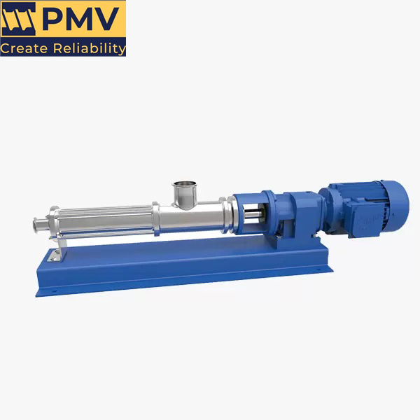
Hygienic Twin Screw Pump, More Commonly Known as Sanitary Twin Screw Pump. The hygienic twin screw pump is an advanced pumping solution designed for applications requiring high hygiene standards. It is generally know as a sanitary twin screw pump,and specifically developed to handle sensitive and viscous fluids in industries such as food and beverage, pharmaceuticals,…
-
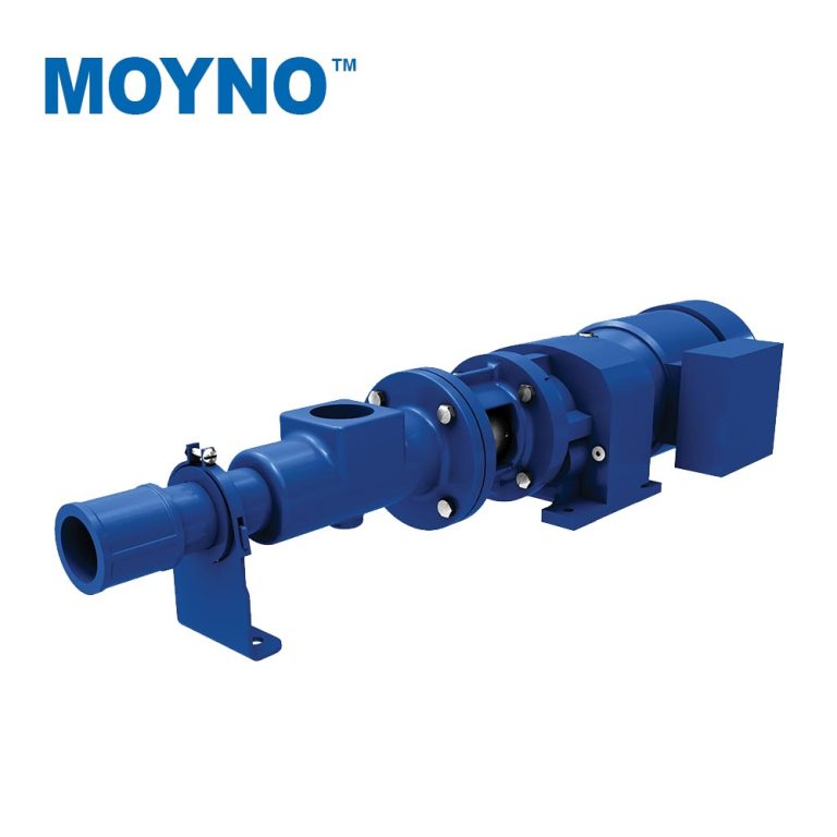
MOYNO Model 2000 HS Large Screw Pumps
2000 HS Large Screw Pumps The 2000 HS System combines high pump efficiency with low discharge pressure to provide unmatched performance in high solids sludge cake transfer. Compared to hydraulically driven, piston ram type pumps and open conveyors, the 2000 HS System requires a much lower capital investment, lower operating costs and less maintenance. People…
screw pump diagram
The key components of a screw pump are:
-
- Casing – This is the outer housing that encloses the screw rotors.
-
- Inlet Port – The opening where the fluid enters the pump.
-
- Outlet Port – The opening where the fluid exits the pump.
-
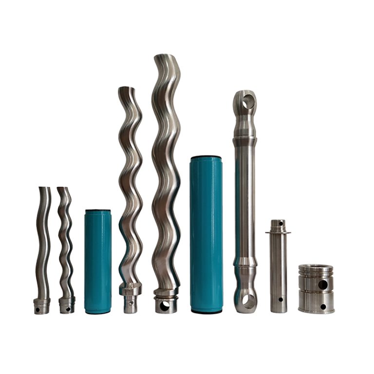
- Screw Rotors – These are the helical screws that rotate and displace the fluid through the pump. They typically consist of two intermeshing screws.
-
- Timing Gears – These gears synchronize the rotation of the two screws.
-
- Bearings – Support the screw shafts and allow them to rotate.
-
- Seals – Prevent leakage between the inlet and outlet.
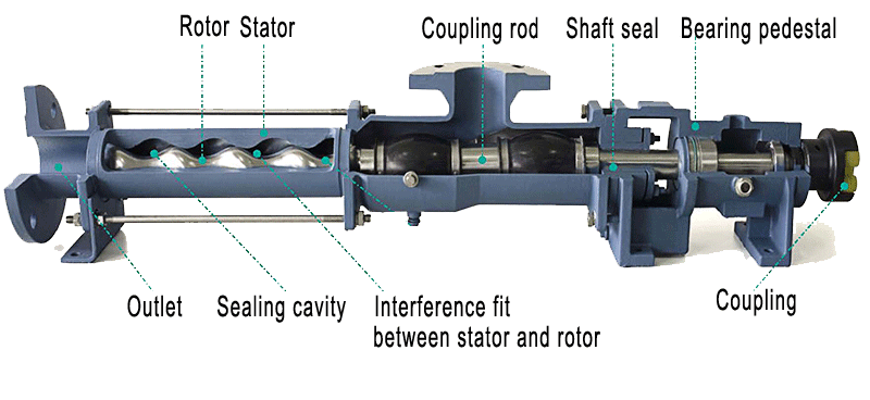
Screw pumps use the rotational motion of the helical screws to draw in fluid at the inlet and positively displace it through the pump to the outlet. They are commonly used to pump high-viscosity fluids like oils, grease, and molten polymers. The self-priming and low-pulsation characteristics of screw pumps make them well-suited for these applications.
