[wpseo_breadcrumb]
Hydraulic jet pumps are vital components in various industrial applications, primarily used for fluid transfer and mixing. Understanding the cavity of a hydraulic jet pump is essential for optimizing its performance and efficiency. This article delves into the structure, functioning, and significance of the hydraulic jet pump cavity.
Structure of the Hydraulic Jet Pump Cavity
The hydraulic jet pump cavity is designed to facilitate the mixing of high-pressure fluid with low-pressure fluid. Its structure includes:
- Inlet Section: This is where the working fluid enters the pump. It is crucial for ensuring a smooth flow into the cavity.
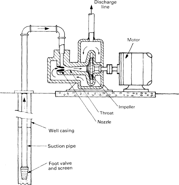
- Jet Nozzle: Positioned at the inlet, the nozzle accelerates the high-pressure fluid, creating a jet that draws in the surrounding low-pressure fluid.
- Mixing Chamber: This is the main cavity where the high-pressure jet interacts with the low-pressure fluid, promoting effective mixing.
- Diffuser Section: After mixing, the fluid flows into the diffuser, where the velocity decreases and pressure increases before exiting the pump.
Functioning of the Hydraulic Jet Pump Cavity
The operation of the hydraulic jet pump cavity can be summarized in the following stages:
- Fluid Entry: The high-pressure fluid enters through the inlet and passes through the jet nozzle.
- Jet Formation: The nozzle converts pressure energy into kinetic energy, forming a high-velocity jet.
- Induction of Low-Pressure Fluid: The high-velocity jet creates a vacuum that draws in low-pressure fluid from the surrounding area.
- Mixing Process: Within the mixing chamber, the high-pressure jet and the low-pressure fluid mix thoroughly, resulting in a homogeneous mixture.
- Fluid Discharge: The mixed fluid then enters the diffuser section, where it slows down, allowing for pressure recovery before being discharged from the pump.
Significance of the Hydraulic Jet Pump Cavity
The design and functionality of the hydraulic jet pump cavity are crucial for several reasons:
- Efficiency: A well-designed cavity enhances the mixing process, leading to increased efficiency in fluid transfer.
- Versatility: Hydraulic jet pumps can handle a variety of fluids, making them suitable for different industrial applications, such as wastewater treatment and chemical processing.
- Maintenance: The simple design of the cavity facilitates easier maintenance compared to other types of pumps, reducing downtime and operational costs.
- Environmentally Friendly: Hydraulic jet pumps operate without moving parts, minimizing wear and tear, and reducing the likelihood of leaks, contributing to a more sustainable operation.
Conclusion
The hydraulic jet pump cavity plays a pivotal role in the functionality and efficiency of hydraulic jet pumps. By understanding its structure and operation, industries can optimize their systems for better performance and lower costs. As technology advances, the design of these cavities will continue to evolve, promising even greater efficiency and sustainability in fluid handling applications.
People also ask
Fill up and submit the below inquiry form, or directly write us an email: info@pumpvv.com